LIDAR-IMU
Xianwei Lv
Section A . VLP32C-IMU
1 Abstract
In the report, we presented the calibration of external parameters for LiDAR VLP-32C and IMU Currently, the only open source calibration package available online is the APRIL-ZJU open-source solution lidar_IMU_Calib, lidar align, and a few others, among which lidar align has low accuracy in listening and speaking, So in the end, we chose Lidar, an open-source solution from ZJU lidar_IMU_Calib, After querying on Github, it was found that it currently only supports VLP-16 line LiDAR, And we are using VLP-32C line lidar, but according to the author's description, it should be easy to expand, That is, modify the /include/utils from the downloaded code:dataset_reader.h and vlp_Common.h file, modify the relevant functions, variables, constants, etc. related to the type of LiDAR. Here are some reference links of code and Blog: code link. Blog.
2 Process
We will show the whole process of calibration, including starting from compiling the code, recording the calibration package, and executing the calibration. Finally give the result.2.1 Clone and Build
First create a ros workspace,and clone the source code for the project and build it.
          mkdir -p ~/lidar_imu_ws/src

          cd ~/lidar_imu_ws/src

          catkin_init_workspace

          git clone https://github.com/APRIL-ZJU/lidar_IMU_calib
Still execute the following commands in the terminal of the src folder (download ndt_omp)
            wstool init

            wstool merge lidar_IMU_calib/depend_pack.rosinstall

            wstool update
Build
Then compile the code and refresh the workspace
          cd …/…
          catkin_make
          source ./devel/setup.bash
2.2 Recording calibration package
To record the calibration package, you need to record the topic of lidar and imu. First start the lidar and imu, and then record the corresponding topic respectively. During the recording process, you should fix the two, and then perform three translations and rotations along the three axes, so that the imu There is sufficient incentive. The recording time is about one minute, and the parameters are filled in the corresponding yaml.
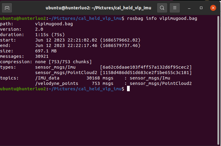
            rosbag  record  -o  cal_held_vlp_imu.bag   /IMU_data  /velodyne_points
            rosbag info cal_held_vlp_imu.bag
2.3 Modify the configuration file and Run
For this calibration program, in addition to changing the configuration of the lidar to 32 lines, it is also necessary to modify its configuration file and startup file. Specifically, it is necessary to modify calib.sh or licalib_gui.launch.
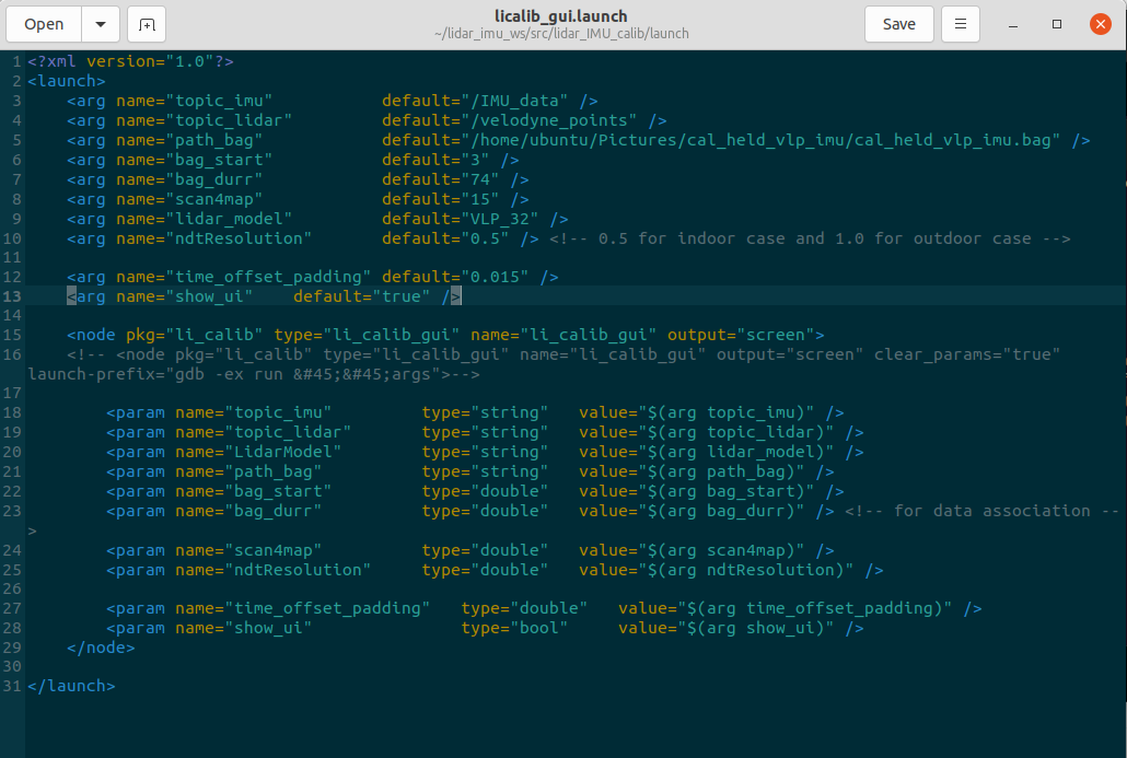
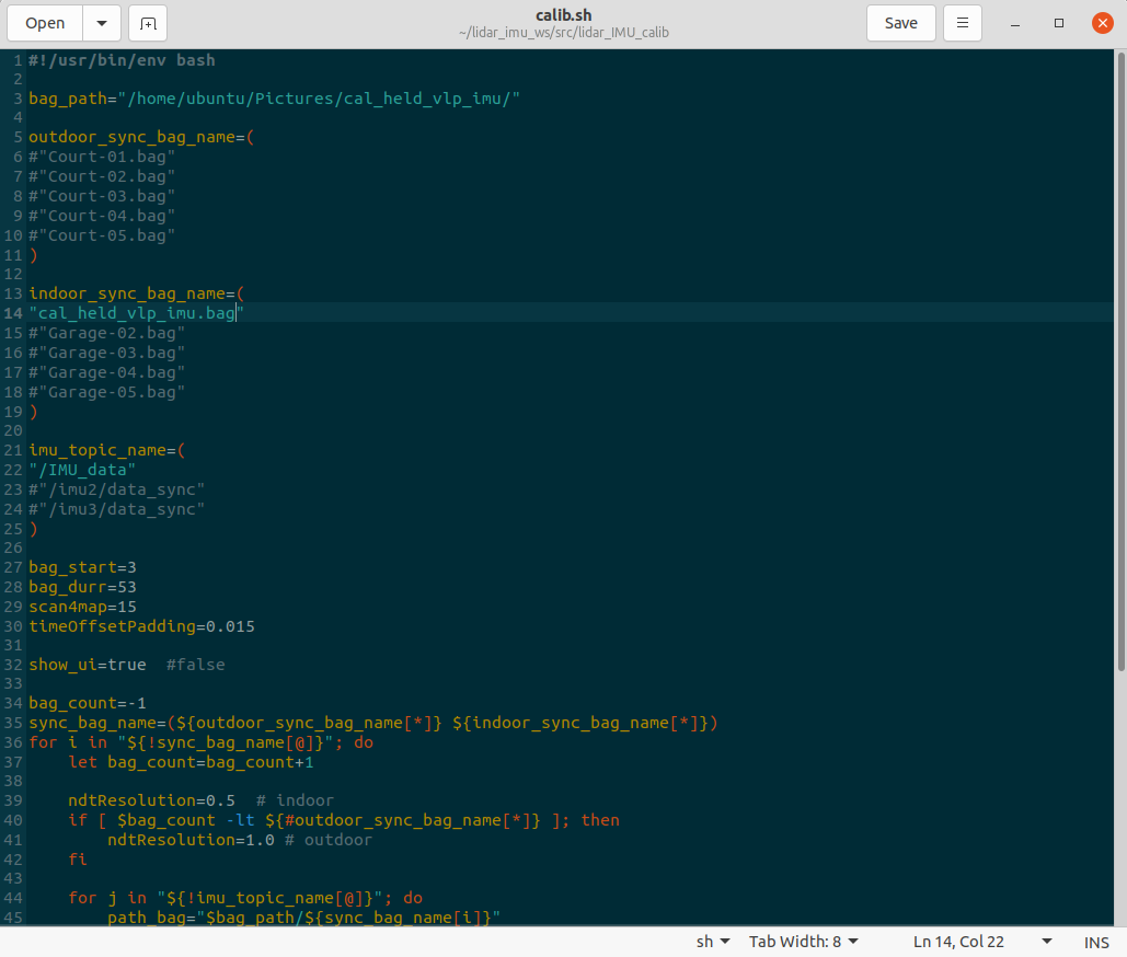
Just modify the topics and corresponding sensor parameters inside. Then run the launch file to start the calibration procedure.
cd lidar_imu_ws/
./calib.sh
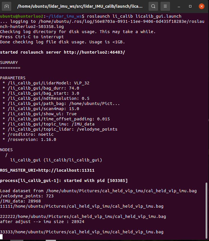
roslaunch li_calib licalib_gui.launch
2.4 process
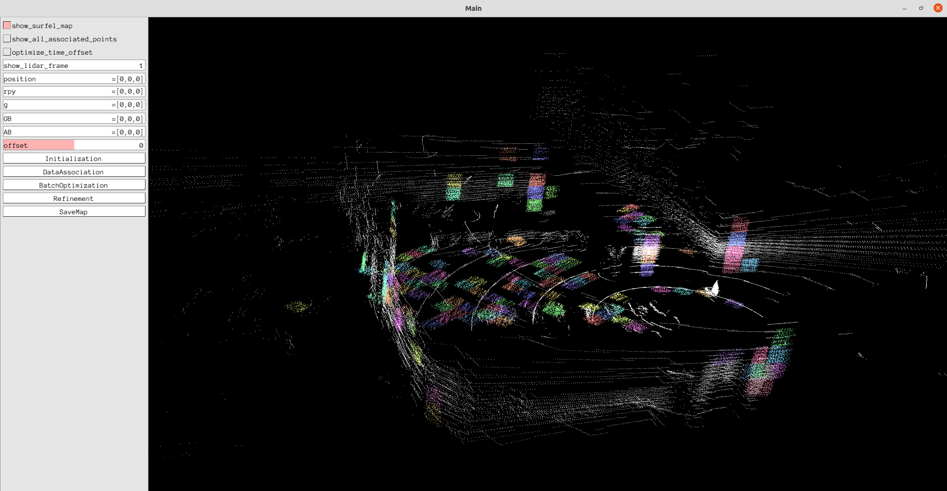
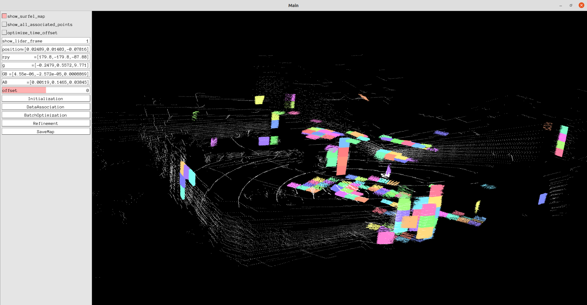
After running the launch file, you can click the button on the left side of the visual interface to perform calibration. The calibration process is divided into five parts, which are shown below.
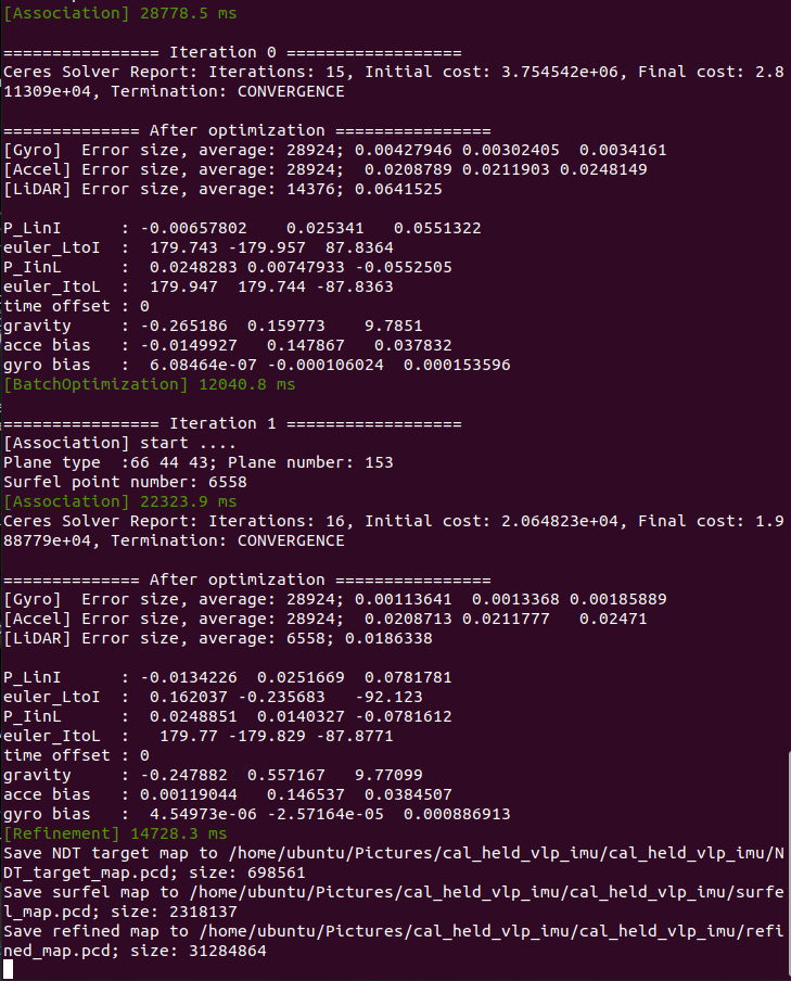
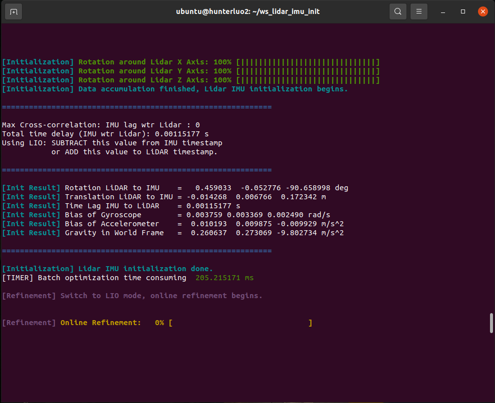
Initialization and BatchOptimization
First initialize the external parameters, the calibration program will estimate a rough external parameter,
and then optimize this parameter. Then perform batch optimization.
Then perform data association, the program will perform feature extraction based on the lidar point cloud, and then perform pose estimation and then associate with the measured value of the imu. Use the associated information for subsequent optimizations.
After data association, the program will refine the external parameters obtained from batch optimization according to the associated information to make the results more accurate.
Finally, the calibrated point cloud result map can be saved and visualized
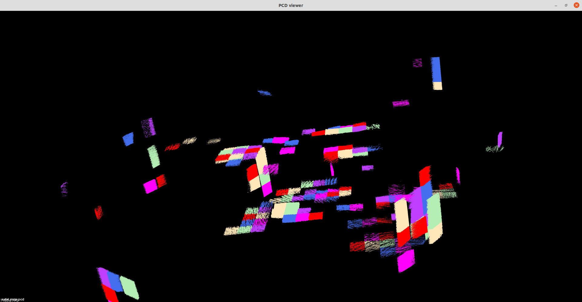
2.5 show pcd
You can view the saved point cloud through the following tools
pcl_viewer refined_map.pcd
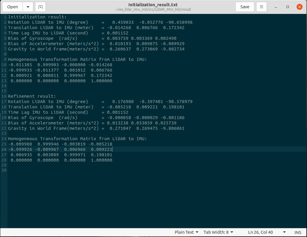
3 Result
After refine, an optimized result will be obtained. The result is Euler angles of three degrees of freedom and translation of three degrees of freedom. We use tools to convert Euler angles into rotation matrices and give calibration results.
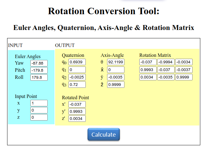
The calibration results are as follows:
            R:

             [ -0.037   -0.9994  -0.0034 ]

             [0.9993  -0.037  -0.0037 ]

             [0.0034  -0.0035  0.9999 ]

             T:

             [0.02489  0.01403  -0.07816]
Section B . MID360-IMU
1 Abstract
In the report, we presented the calibration of external parameters for LiDAR MID360 and IMU We use the open source LI-Init method of the Mars Laboratory of the University of Hong Kong to calibrate the external parameters between the solid-state lidar and the imu. LI-Init is a powerful real-time LiDAR inertial system initialization method. This method calibrates the time offset and extrinsic parameters between the LiDAR and IMU, as well as the gravity vector and IMU bias. The method does not require any targets or additional sensors, a specific structured environment, a priori environment point maps, or initial values for extrinsics and time offsets. Here are some reference links of code and paper: code link. Paper.
2 Process
We will show the whole process of calibration, including starting from compiling the code, recording the calibration package, and executing the calibration. Finally give the result.2.1 Clone and Build
First create a ros workspace,and clone the source code for the project and build it.
          mkdir -p ~/ws_lidar_imu_init/src

          cd ~/ws_lidar_imu_init/src

          catkin_init_workspace

          git clone https://github.com/hku-mars/LiDAR_IMU_Init.git

          cd ..

          catkin_make -j

          source ./devel/setup.bash
2.2 Recording calibration package
To record the calibration package, you need to record the topic of lidar and imu. First start the lidar and imu, and then record the corresponding topic respectively. During the recording process, you should fix the two, and then perform three translations and rotations along the three axes, so that the imu There is sufficient incentive. The recording time is about one minute, and the parameters are filled in the corresponding yaml.
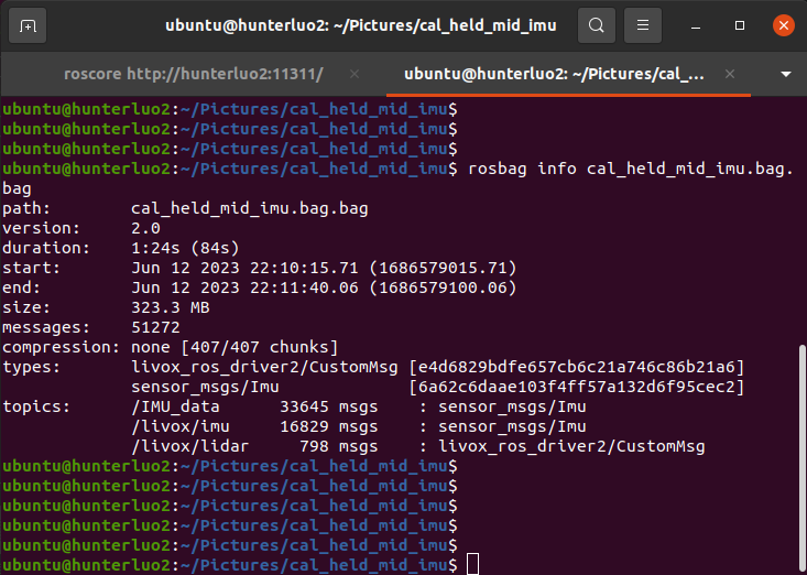
            rosbag  record  -o  cal_held_mid_imu.bag  /livox/lidar  /livox/imu  /IMU_data
            rosbag info cal_held_mid_imu.bag
2.3 Modify the configuration file and Run
For this calibration program, in addition to changing the configuration, it is also necessary to modify its configuration file and startup file. Specifically, it is necessary to modify mid360.yaml
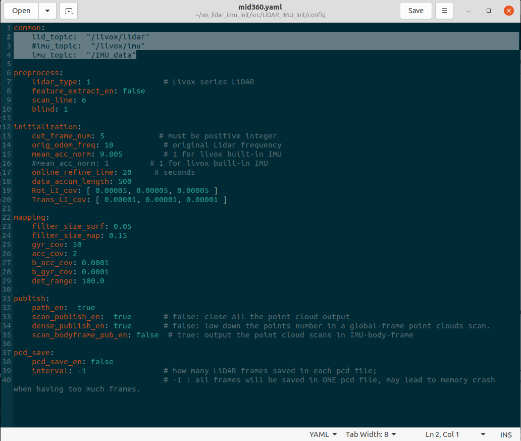
              lid_topic:  "/livox/lidar"

            #imu_topic:  "/livox/imu"

            imu_topic:  "/IMU_data"
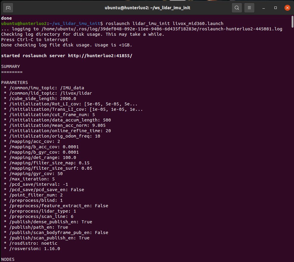
Just modify the topics and corresponding sensor parameters inside. Then run the launch file to start the calibration procedure.
roslaunch lidar_imu_init livox_mid360.launch
2.4 process
After running the launch file,it will automate the calibration processwhich are shown below.
First of all, the program will initialize the angles of three degrees of freedom, so be sure to include three angles of rotation when recording the package, and not too violent, because that will make the program run away and fail
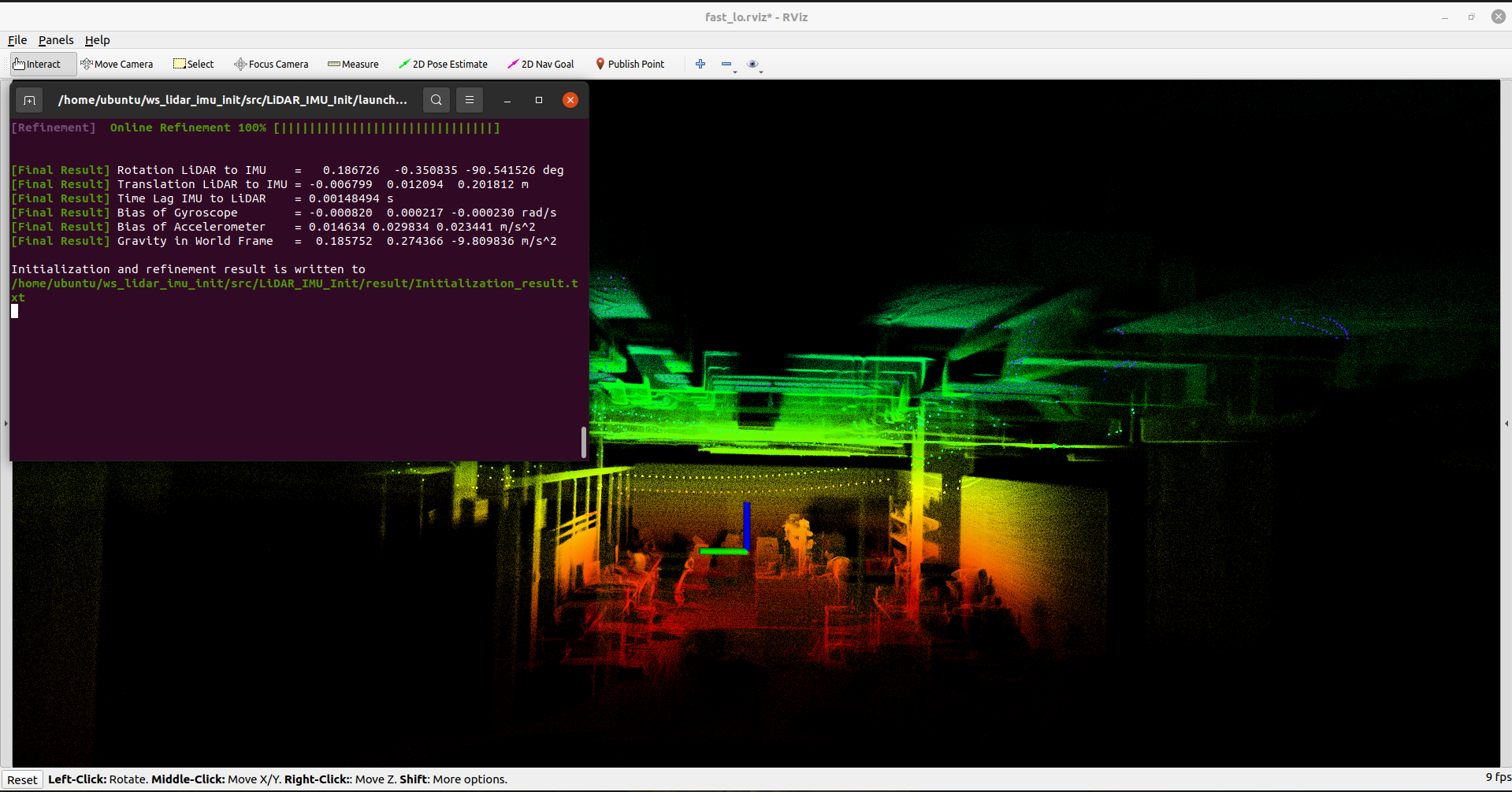
TAfter initialization, the program will refine and build the map online, you can see that the built map is very delicate
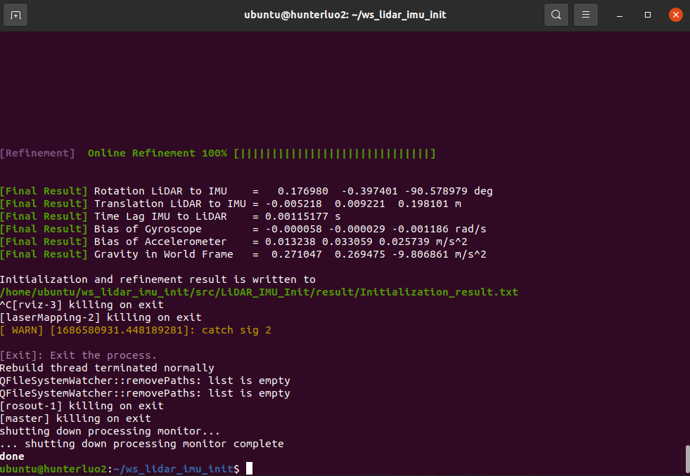
Finally, the calibration result is the external parameter between mid360 and imu. It can be seen that it is very accurate, because our sensor is installed vertically, so the rotation between each axis is 90 degrees, and there is only a z-axis difference. Translation, the calibration result is consistent with the actual.
2.5 show process and scene
The following shows our calibration process and the actual scene of the map.
3 Result
We calibrated the mid360 and the built-in imu and external imu respectively, and the accurate calibration results are given below:
            ex_mid360_in_imu

            Homogeneous Transformation Matrix from LiDAR to IMU:

            0.999907  0.013033  0.003928 -0.001683

           -0.013029  0.999915 -0.001004 -0.028559

           -0.003941  0.000953  0.999992  0.023213

            0.000000  0.000000  0.000000  1.000000
            ex_mid360_ex_imu

            Homogeneous Transformation Matrix from LiDAR to IMU:

            -0.009988  0.999946 -0.003019 -0.005218

            -0.999926 -0.009967  0.006966  0.009221

             0.006935  0.003089  0.999971  0.198101

             0.000000  0.000000  0.000000  1.000000